
Difficulty
Difficult
Steps
81
Time Required
03:00:00

In Progress
This guide is currently being written. Reload periodically to see the latest changes.
Quiz
0
Introduction
Bunny and Bear Short Ears (BNBSX) MK3S Geared Extruder is an advanced, geared extruder for upgrading the Prusa MK3S and MMU2S printers.
--
STL files for this extruder are at https://www.thingiverse.com/thing:362699...
Materials needed and Amazon shopping list are in file attached to end of this guide.
--
Benefits of this extruder.
Compared to the Prusa R4 extruder...
- Geared 54:16 drive for more consistent extrusion
- Isolates filament from extruder motor heat
- Corrected filament path/Bontech alignment
- Highly constrained filament path for flexible material
- Supports tightly sculpted PTFE tube
- Lower total mass by about 80 gm
- Reduces moment arm by moving motor closer to x-axis.
- Isolates filament from extruder motor heat.
- Swappable filament sensor systems (armature for single filament, internal lever for MMU2S)
- Internal lever eliminates bulky Prusa sensor chimney
- Internal lever allows full opening of idler door
- Single screw tuning of MMU2S filament sensing
- Single media MK3S sensor armature eliminates steel ball rattling
- Provisioned for LED filament sensor indicator mod
- Only one magnet needed for filament sensor
- Easy motor plate and hot end removal for service
- Hot End PTFE tube changeable without disturbing XYZ calibration
- Separately printable hot fins for heat resistance
- Hot fins tightly encircle hot end.
- Multiple hot end choices, E3DV6, Volcano, or Mosquito hot ends
- Air plenum remains optimum whether E3D or Mosquito installed
---
Use the BNB Universal X-carriage for mounting this extruder. https://www.thingiverse.com/thing:361059.... BNB Universal X-carriage has cable management features to reduce risk of hot end cable damage during XYZ calibration.
Before doing XYZ calibration, verify that hot end cables will clear head bed clamp with print bed pulled max forward and x-carriage max left.
--
Because extruder motor is pushed so far back, this must be mounted on Short Ears version of Bear x-axis to clear the motor x-end. Normal Bear x-axis mounts will impinge against motor. Short Ears x-ends are included in this project.
--
Once installed, you also must set and store e-steps for 54:16 gearing by sending g-codes to printer. Both microstepping and e-steps must be adjusted.
Use a terminal to make the settings and verify they have been accepted. For instance on a BNBSX extruder you would issue (Don't send the comments after the //)
*M350 E16 //set extruder microstepping
*M92 E473 //set e-steps M500 //store the settings
*M503 //read current settings to verify the extruder motor microsteps and e-steps are 16 and 473
NB: M350 must be performed BEFORE M92. Otherwise, M350 on more recent firmwares will also alter existing the e-steps value.
Once you have verified e-steps and microstepping are correct, you can proceed with Live-Z calibration.
Videos of BNBSX in operation
--
-
-
Guide is still a work in progress. Complex or Bunny Science specific steps are completed, but some generic build steps have yet to be written or illustrated.
-
Experienced builders can already proceed, but if you need instructions for generic tasks like attaching a cooling fan, PINDA or hot end, those are not yet in guide.
-
-
-
Print BNBSX parts in PETG with 4 perimeters, 5 top shells, 5 bottom shells, 20% gyroid fill. Bunnies suggest 0.15 mm layer heights for best surface appearance.
-
BNBSX Extruder Plated 3mf file has the extruder parts pre-plated including spares of fragile bits. (Files at https://www.thingiverse.com/thing:362699...)
-
Print BNB Short Ears X-ends for this extruder. (STL's included in this extruder project)
-
Print BNB Universal X-carriage for this extruder. (STL's at https://www.thingiverse.com/thing:361059...)
-
-
-
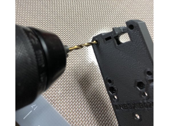
Clear out each 3mm screw hole with a 3 mm drill bit to make bolt insertion easier.
-
There are also a few 2 mm holes to drill.
-
Some 3 mm holes in motor plate gearbox have a thin, sacrificial membrane to improve geometry.
-
Don't drill out holes intended to be directly threaded like the noctua fan or IR sensor module mount holes.
For me there were only a few that were obvious they needed to be drilled out. But a diagram would not be a bad idea
Chris Champeau - Resolved on Release Reply
might Be good idea to have a diagram of which holes are which, just to Be sure.
jonathanitall - Resolved on Release Reply
-
-
-
Draw nuts into hex pockets rather than trying to push them into position.
-
Be sure nut is rotationally aligned with hex recesss as you draw it in. Misalignment will damage the pocket.
-
Washer at bolt head reduces damage to plastic. This is especially important on the motor plate gearbox. Do not over tighten. Just get the nut fully seated. Once nut is seated, remove bolt and washer.
-
If POLYCARB print, use minimal force when drawing in nuts. Polycarb is more brittle than PETG and can snap. If nut will not fully seat, gently melt it into place with a 260C soldering iron tip.
-
-
-
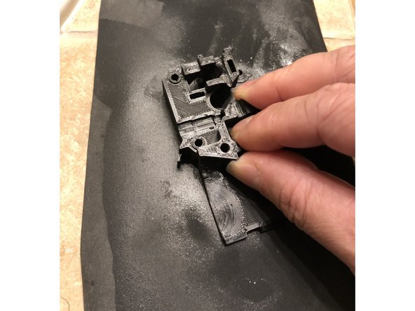
Printed parts mate together more accurately and securely if their mating surfaces are actually flat. Less torque is needed to secure parts whose mating surfaces are in good contact.
-
Flatten mating surfaces that were printed on textured print plates by wet lapping with wet/dry 600 sandpaper on flat glass plate.
-
Do not lap so much that you dimensionally change size or shape. Remove just the "high" points of the texture
-
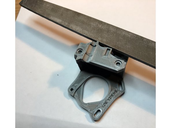
Remove retraction zits from top surfaces or irregular shapes with light strokes of a metal file. Just one or two strokes are all you need.
-
Be mindful of raised features like index pins when flattening surfaces! Do not damage raised features
-
-
-
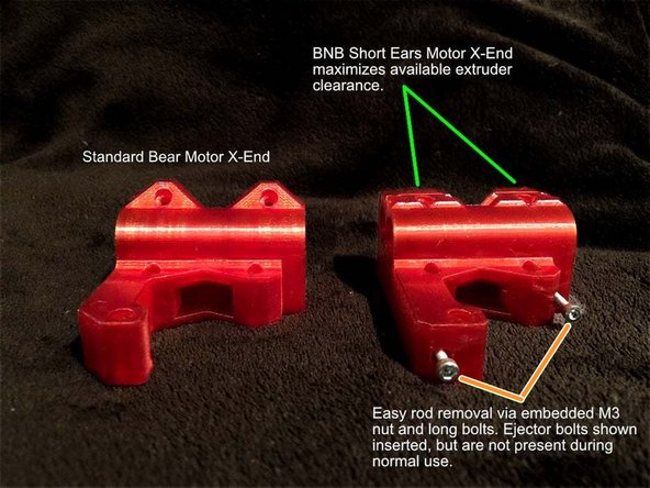
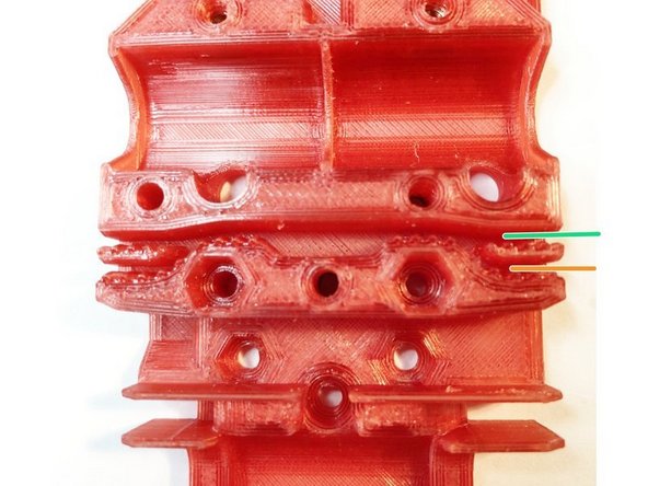
Bunny Science enhanced versions of the Bear x-ends are provided with BNBSX extruder. These "short ears" x-ends feature...
-
Low profile bearing mount clamps that don't obstruct the BNBSX extruder's rearward positioned motor.
-
Linear rod removal assist pusher bolt feature
-
Bear x-axis easy belt tension adjust system
AHA! success. I moved my belt to the upper retainer on the mount plate and adjusted the x drive pulley to align better with the belt in it's new home. (It was rubbing on the motor side) Now the self test passes with no more troubles.
this is the follow up not the original
Chris Mosdal - Resolved on Release Reply
I should note that stock prusa x-ends worked great with the extruder body and everything cleared it with ease. I am not running the bear frame setup so even though I printed these parts, I did not end up using them
Chris Champeau - Resolved on Release Reply
AHA! success. I moved my belt to the upper retainer on the mount plate and adjusted the x drive pulley to align better with the belt in it's new home. (It was rubbing on the motor side) Now the self test passes with no more troubles.
I very much wish I had read this before printing and installing the Bear ends. I am getting a full 250mm travel on the X-axis but the new firmware 3.12.2 has hung up on me because the self test fails. I gets as far as the X-axis check and fails right afterward. I think it sees too much movement from end to end. At the time I am writing this I have not yet solved the issue but I will get it done and try to get the solution posted here after.
-
-
-
4 of M3 x 8mm cap end screws. (Socket head screws are too large profile)
-
10 of M3 hex nuts
-
2 of M3 Nylock nuts
-
5 of M3x18 screws
-
20 tooth GT2 Idler (or re-use stock Prusa smooth Idler)
-
3 mm x 15.5 mm shaft rod
-
-
-
Original Bear axis instructions by Grégoire Saunier are good adjunct to these instructions. Bunnies will focus on differences between Short Ears and the original Bear x-axis
-
-
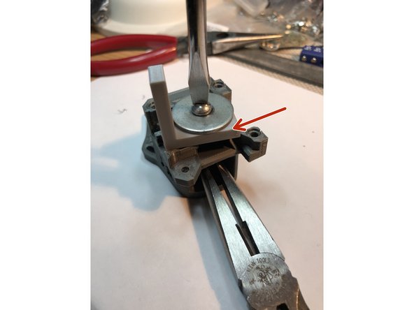
Short Ears assembly is very similar, but clamp screws are shorter, and Bunnies recommend putting x-axis on /off Z-rods WITHOUT trapezoid nuts installed.
-
-
-
Clear out linear rod mounting holes with 8 mm drill at low RPM.
-
Draw in M3 nut for each x-end clamp WITHOUT LMU8 bearings in place. Leaving out the bearings is VITAL during this step. This lets two sides of clamps abut and support each other during process.
-
With the bearings in place, clamp ends cannot abut each other during nut draw-in process. The plastic clamp WILL SNAP before nut can be drawn in.
-
Do not over tighten clamps when bearings inserted. The clamp gap will never close with bearings inserted. Attempting to close gas will break clamp.
-
Repeat for other x-end.
-
-
-
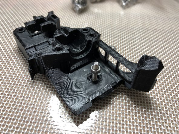
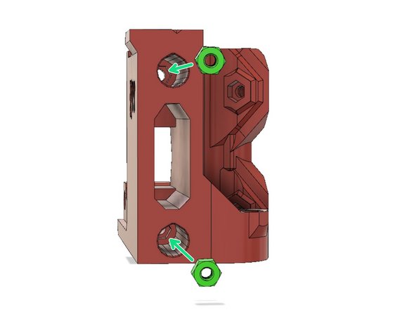
Insert M3 hex nuts to later accept T-nut mounting screws.
-
T-nut refers to large, black Delrin nut that rides up and down z-axis screws.
-
Repeat for other x-end.
-
The nut in pocket tends to fall out. Temporarily hold it in place with an M3 screw.
-
-
-
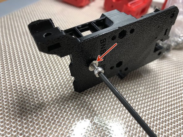
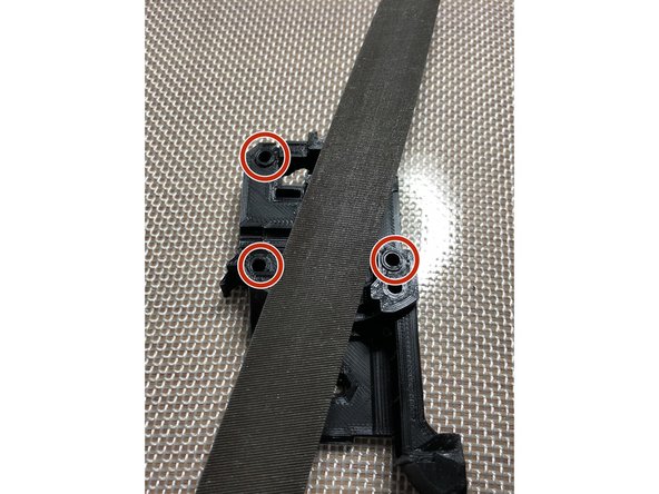
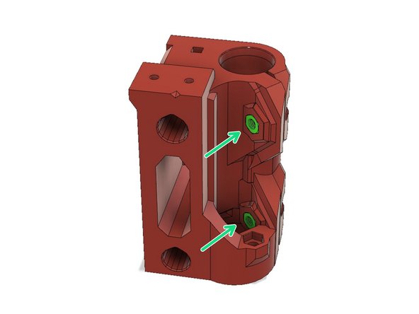
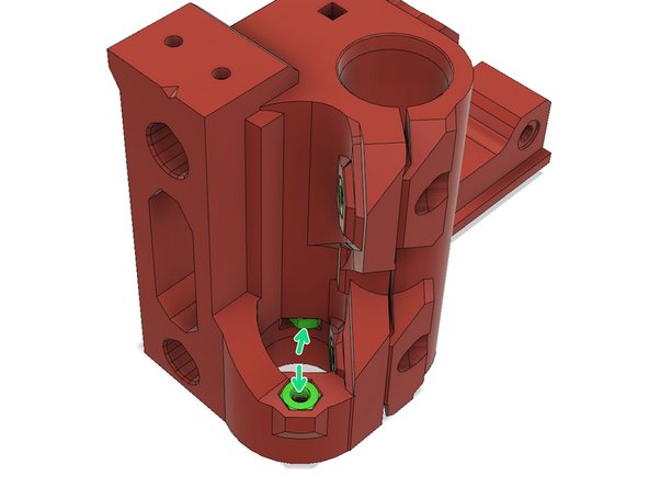
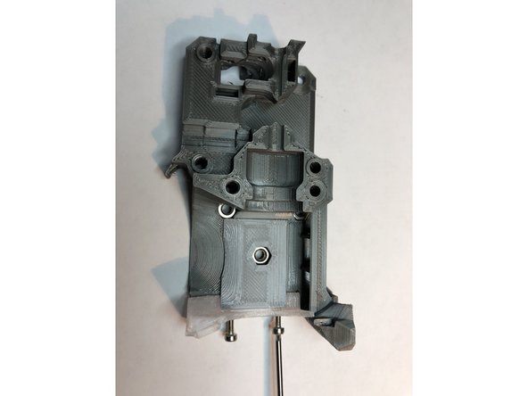
Motor X-end has hex pockets at end of each linear rod hole. Draw one M3 nut into each pocket.
-
These nuts can engage a long M3 screw to help eject rods. Alternatively, use variable speed drill to spin linear rods in/out.
-
Idler X-end does NOT have M3 nut pockets. Do not insert M3 nuts into idler x-end. Length adjustment M3 screws directly thread into Idler X-end plastic.
-
-
-
Spinning linear rod in and out with a drill is MUCH easier than pushing or pulling rods into position.
-
-
-
With clamps completely loose, insert two LMU8 bearings into each x-end.
-
During insertion, align LMU8's so each pair has their rows of bearings offset by 45 degrees.
-
-
-
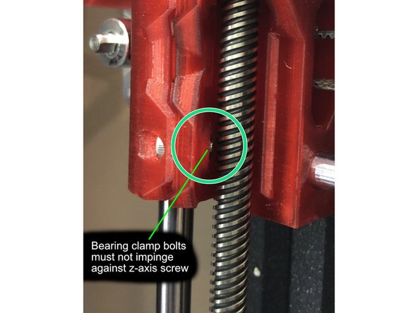
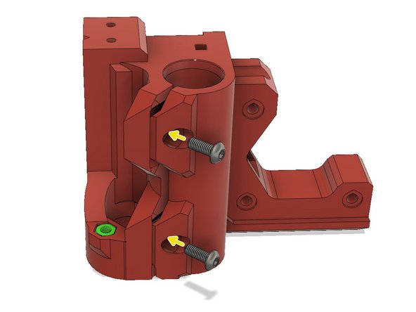
M3 x 8 mm CAP head screws to secure bearing clamps. Snug, but don't torque tight.
-
M3 screws longer than 8mm here will damage Z-axis screw rod. Bunnies recommend verifying clearance.
-
Continue checking that clamp screws do not extend much beyond nuts during tightening.
-
Photo shows hex socket screw. Current recommendation is round cap head screw. Hex socket screws sometimes needed heads filed to be flush with x-end.
-
-
-
If using hex head M3 screws, you may need to file the top clamp screw head to clear motor..
-
Cap head screws are lower profile and less likely to be motor clearance issue.
-
-
-
Precheck idler holder is able to freely slide in and out of idler x-end. Shave and smooth idler holder as needed.
-
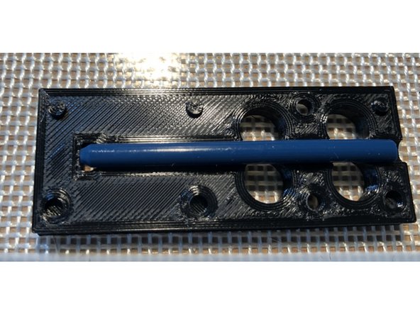
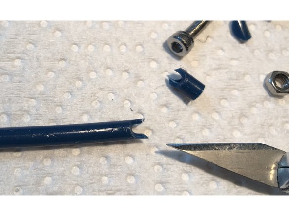
Secure idler pulley in idler holder with 3 mm dowel rod.
-
Dowel rod should not extend beyond sides of idler holder.
-
Place two M3 Nylocks into idler holder. End with nylon should point towards opening of idler
-
Insert idler holder into idler x-end
-
Insert two M3 x 18 screws through idler x-end into nylocks, but only tighten x 2 turns. These two screws are used to adjust x-belt tension.
-
Thread two M3 x 18 screws through idler x-end to just touch linear rods. These are used to fine adjust x-axis length, but you will probably just leave them barely touching linear rods.
While this step is pretty straight forward, pictures of this step would be nice
Chris Champeau - Resolved on Release Reply
-
-
-
Remove retraction zits and other irregularities from flat mating surfaces.
-
Two strokes with a metal file is usually enough.
-
-
-
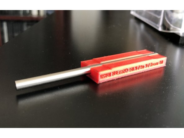
Prepare 5 mm diameter shaft rod, Length 55 mm, Pulley Flat 0 to 9 mm, Bondtech Flat 42 mm to end. See https://www.thingiverse.com/thing:359520... for shaft cutting guide and instructions
-
Shaft_Cutting_Guide_Bunny_and_Bear_Short_Ears_55-9-42_mm is the cutting guide for this BNBSX "Short Ears" MK3S extruder
-
Most 5 mm shaft rods are slightly too large in diameter to fit through 5 mm bearings. Chuck shaft blank in drill and sand down shaft diameter. Entire length of shaft must easily pass through 1050ZZ bearing.
-
Ideal BNBSX gear shaft is slightly shorter at 53.5 mm, but cut at 55 mm and adjust after test fitting. BNBSX differs in that it needs clearance beyond rear of shaft for internal sensor lever.
-
BONDTECH shaft flat is most difficult to get correct. Grind only 0.35 mm deep. Too deep and screw will not reach. Too shallow and screw head hits other Bondtech.
-
-
-
Draw two 1050ZZ Miniature Steel Bearings 5x10x4 mm into front and back bearing mounting holes
-
Use M5 bolt, two washer, and a nut to draw in bearings. Resistance to bearing insertion should be moderate. If you find yourself torquing bolt hard, something is awry. Remove the bearing and recheck for stray filament bits
-
Temptation is to press bearings in too far. They won't be flush with plastic surface. Just get them seated. Stop pressing as soon as you feel bearing bottom. Going too tight will cause misalignment and friction problems.
-
If bearing is stuck in hole and you need to remove it, tap it out using M5 Hex driver as punch.
-
Front bearing is easy, but rear bearing requires drawing against uneven surface. Use flat object or printed BNBSX Bearing Pressing Aid piece to support large washer evenly.
-
Pass a 5 mm shaft through both installed bearings. Shaft should spin easily. If not, back out the bearings very slight using a 5 mm hex driver as a punch. Adjust alignment and depth of bearings until you achieve free motion.
-
Bearings when aligned are low friction. You should be able to hold the shaft horizontally. Tap the motor plate and watch motor plate swing back and forth for about ten seconds.
-
The bearings will not fall out. Shaft locks installed later will stabilize their depth in mounting holes.
This step should appear before MMU filament insert step as the insert sits proud of the plate face and interferes with press operation.
Chris Gorman - Resolved on Release Reply
-
-
-
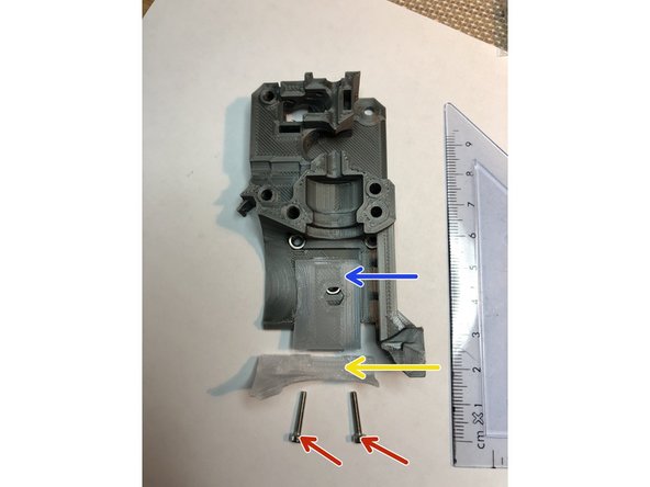
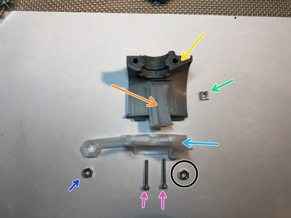
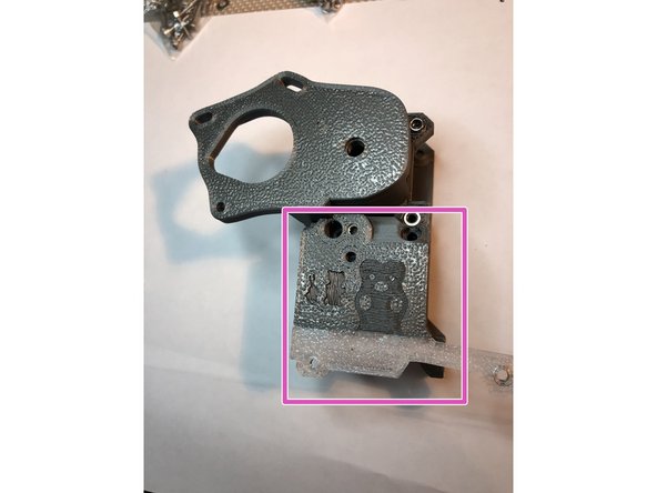
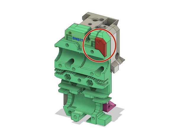
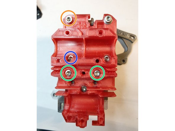
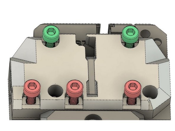
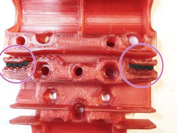
Three regular M3 nuts and one M3 Nylock must be installed.
-
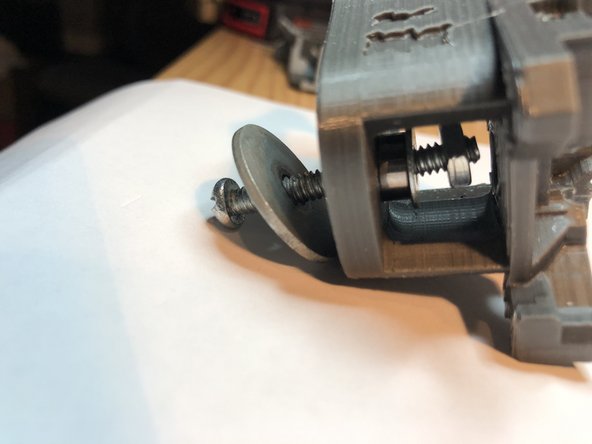
On the Motor Plate Gearbox, it is absolutely vital to use washers with your drawing bolt. Otherwise, head of bolt will damage these index depressions around the bolt holes. Damage makes mating motor plate with extruder body difficult.
-
M3 Nylock for idler door bolt. We use Nylock here because idler door bolt is not secured under tension. It needs Nylock to help keep it in place.
-
Regular M3 Nut
-
Regular M3 Nuts, but be mindful of excessive bolt length during drawing in process.
-
-
-
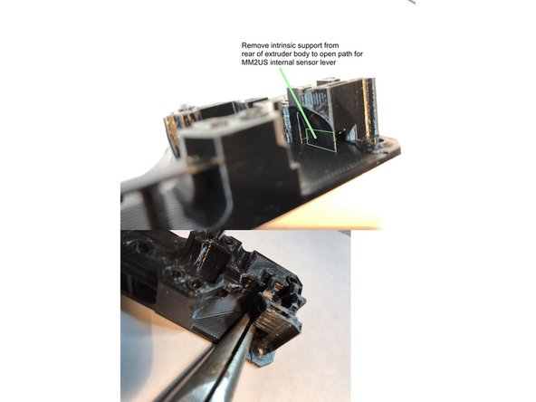
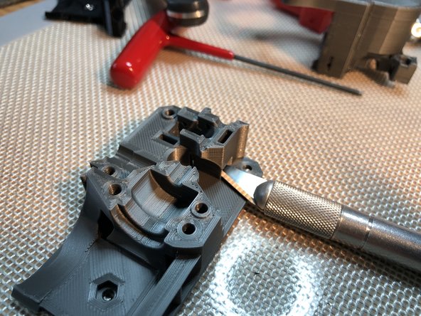
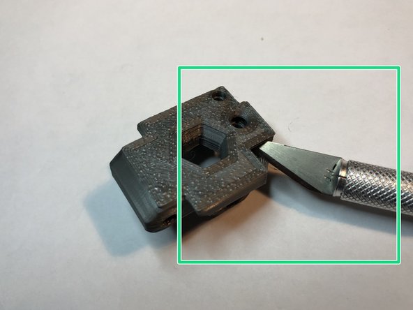
Extruder Body is printed with an intrinsic support. Remove intrinsic support with knife and pliers.
-
Lap rear surface of Extruder Body to flatten its x-carriage mating surface.
-
Use metal file to knock off plastic zits on front mating surfaces. Be mindful of the three index pins
-
-
-
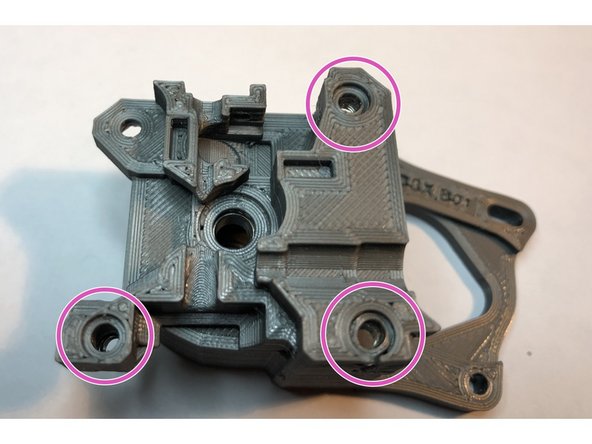
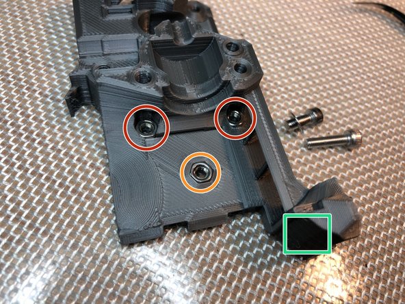
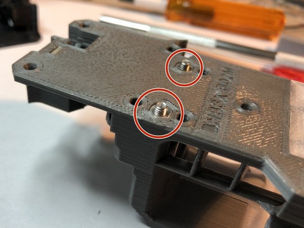
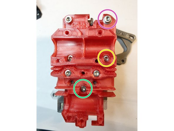
Install three M3 nuts. These will attach extruder to x-carriage.
-
Lower M3 nut is easy to install
-
Upper two M3 nuts are more challenging. Begin with M3 x 12 mm screw and washer. Partially seat nut with longer 12 mm screw. Switch to shorter M3 x 8 mm screw to fully seat nut.
-
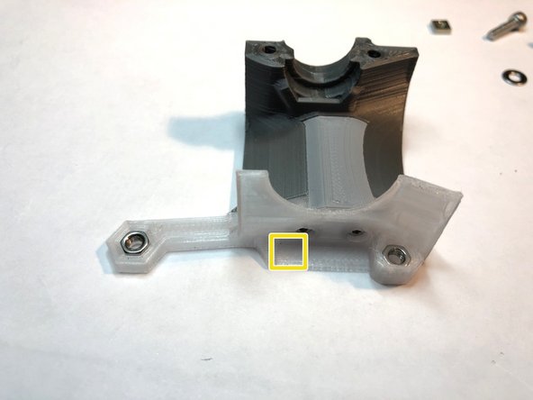
M3 Nylock goes here for version B03.
-
PINDA clamp nut pocket differs from other nut pockets. Forcefully pulling in nut will split print layers here. Clean / enlarge nut opening with needle file until nut slides in easily. Do NOT attempt to pull in nut with bolt tension.
-
I cheat a bit here by melting a regular M3 nut into the pocket and pushing it back out while still hot. That enlarges the pocket so M3 Nylock can slide in. Key is the nut must SLIDE in without force.
-
-
-
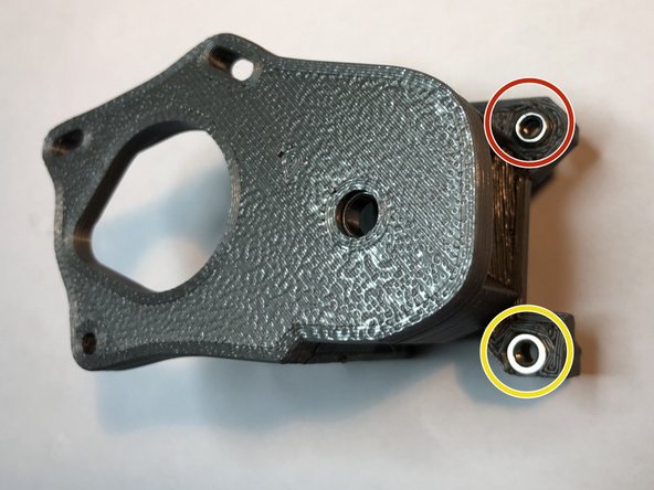
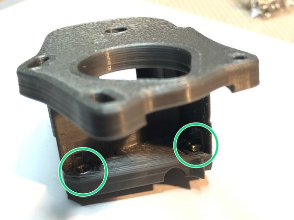
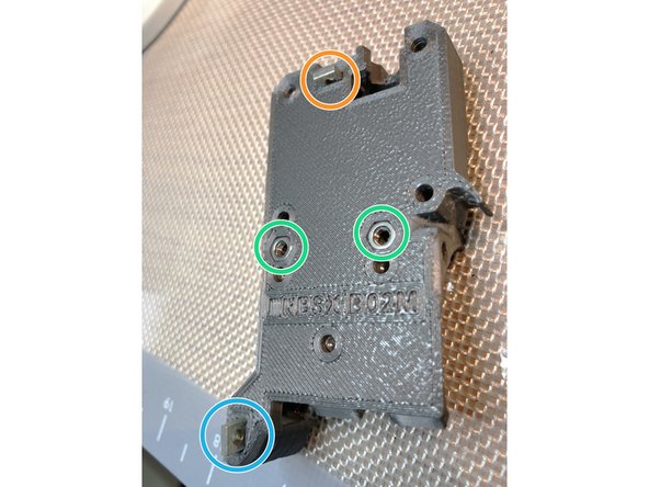
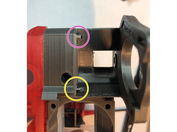
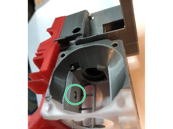
Insert hot end cover mounting M3 nuts. These nuts must be fully seated and not protrude beyond rear surface of extruder body.
-
Top cover M3S nut
-
PINDA mount used M2S here in older versions, but made PINDA clamp prone to loosening after several hundred hours printing.
-
You may need to clear out square nut pockets with a x-acto knife before square nuts easily pass.
-
-
-
E3D Plenum Plate is held in position by a tab on each of its ends
-
Hot fin can be printed in higher temperature material like ABS or Polycarbonate to better resist heat. Another strategy is to have spare hot fins pre-printed, but higher temp material is recommended option.
-
Two M2 x 12 mm screws attach hot fins to extruder body
-
Just seat and slightly snug the M2 screws. They are threading directly into plastic.
-
E3D Plenum Plate is omitted and special hot fin used if Mosquito hot end is installed.
-
-
-
For stand-alone, single filament use, armature with bearing detects filament ABOVE Bondtech drive gears.
-
For MMU2S, internal lever senses filament separating Bondtech gears. MMU2S uses this to know when filament has reached drive gears.
-
You can swap filament sensing system WITHOUT a full extruder tear down. Simply remove motor plate and IR sensor board. Then, swap armature and internal sensing lever and move magnet. For now, build the option that matches your needs.
-
-
-
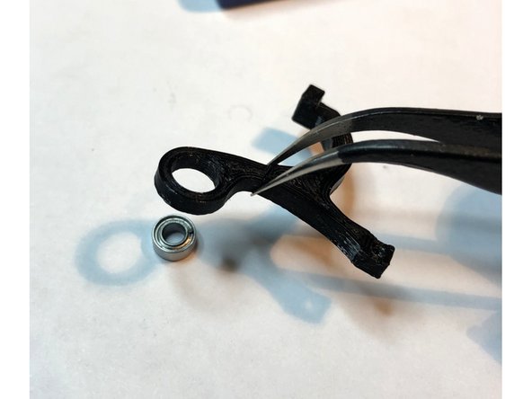
Post print process armature only with a knife. Do not use hot air or you risk damaging its interruptor fin.
-
Press pivot MR63ZZ 3x6x2.5 mm miniature bearing into BOTTOM of armature.
-
Top of armature's bearing mount is smaller diameter. Do not press bearing in from top. Be careful not to break the interruptor fin.
-
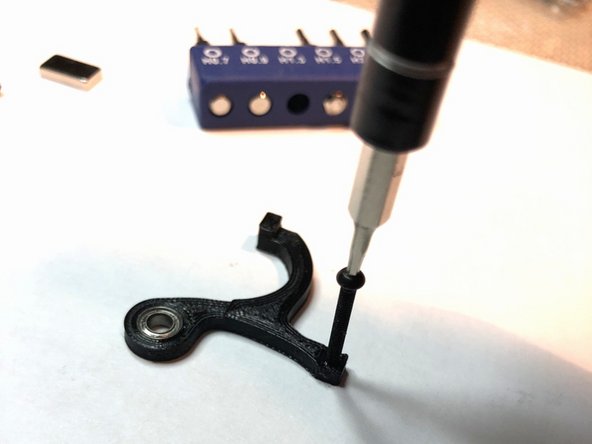
Attach filament sensing MR63ZZ bearing to armature with M3 x 6 mm screw. Bearing should be secure but keep screw loose enough for free bearing rotation.
-
Some hex socket head screws have slightly longer head that limits armature swing range. That results in filament sensor stuck in "on" position when motor plate is attached. If you encounter this issue, file away part of screw head or use a smaller head screw like a cap head M3 x 6.
-
Armature must be printed in opaque color. Bunnies recommend PETG black.
-
-
-
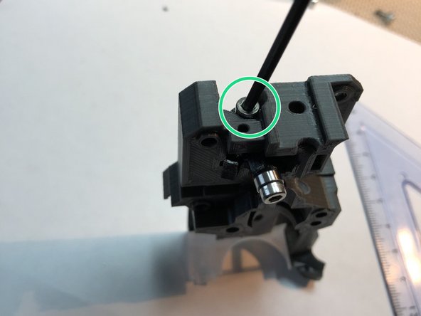
Insert armature into sensor pocket of extruder body
-
Secure through pivot bearing with M3 x 8 mm screw. Be gentle. This screw threads directly into plastic.
-
The M3 screw will never prevent armature from being able to tilt vertically. Do not over tighten attempting to lock down armature. Just get screw full seated.
-
The armature must move freely. It is normal for it to be capable of wobbling up & down in its pocket.
-
-
-
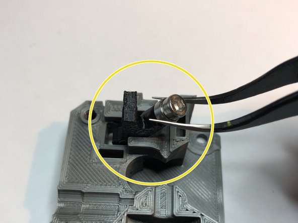
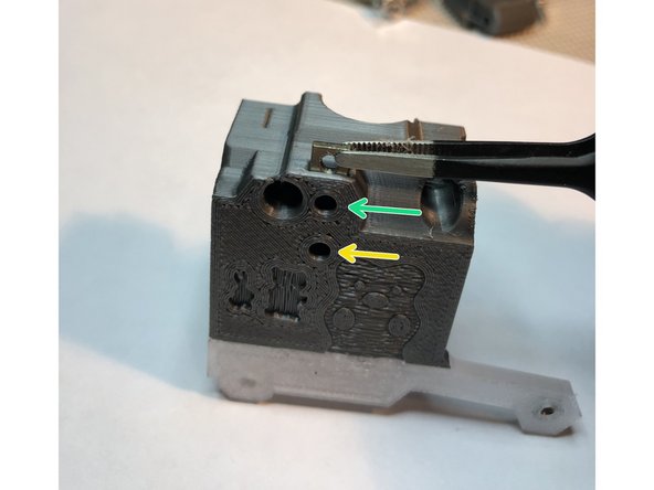
Insert small, 5 x 10 x 2 mm magnet, from Prusa MK3S sensor system, into pocket right of armature
-
Bunny Science needs only a single magnet. Magnet pulls bearing into filament path. Filament pushes bearing out of path and swings armature. Interruptor fin triggers MK3S IR filament module (to be installed later)
-
Magnet strongly attracts bearing making armature less prone to rattling during accelerations.
-
When using the single filament armature, you will also place one MR63ZZ Miniature Steel Bearing as a spacer on the idler door hinge screw.
-
-
-
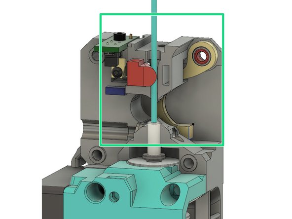
Internal sensor lever is sensor configuration for MMU2S printers. This replaces bulky external chimney with internal lever.
-
You may alternatively use the cumbersome Prusa chimney, but Bunny Science internal sensor lever is sleek and allows full opening of idler door.
-
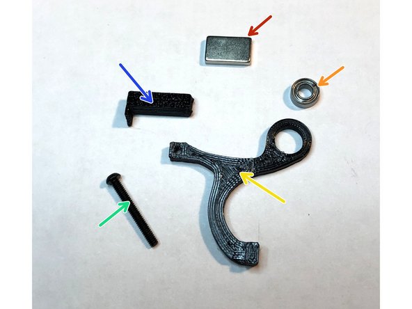
2 x 5 x 10mm magnet from Prusa MK3S sensor system
-
MR63ZZ Miniature Steel Bearing 3x6x2.5 mm
-
Internal sensor lever for MMU2S
-
M2 x 16 mm BLACK STEEL ALLOY screw cap hex screw. This screw MUST be strongly attracted to magnet. Stainless steel will not work. Also, use cap head here for needed compactness.
-
Optical interruptor bar should be printed in opaque color, preferably black.
-
-
-
Use sharp blade and /or emory board to clean stringing from optical fin. Try not to alter fin dimensions during cleaning.
-
Small leg of the fin does the actual optical interruption. It drops down and blocks light path when filament slightly opens idler door.
-
Several copies of this piece are plated in extruder 3mf. It is a good idea to have extras, especially your first time assembling the extruder.
-
-
-
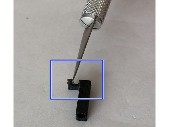
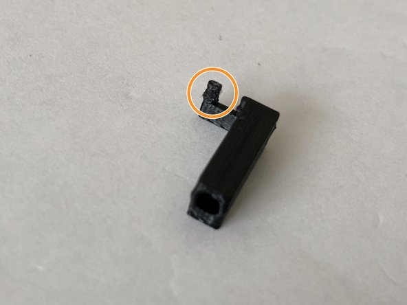
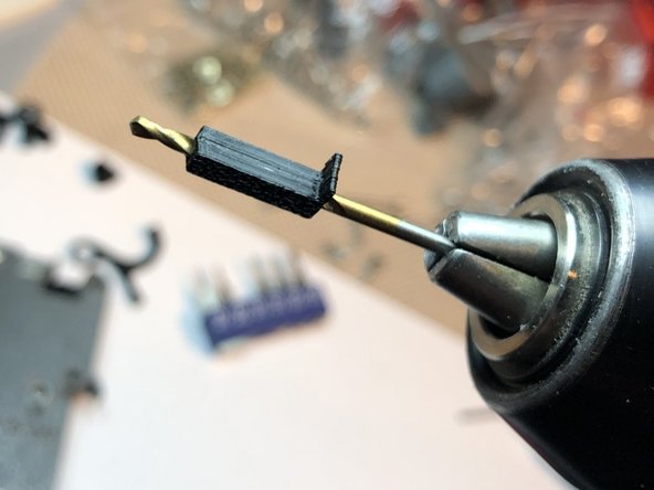
Use 2 mm drill to clear screw bore of optical interruptor bar. M2 Screw must readily slip through the bore.
-
Just as with armature, do not use hot air for post print processing of this piece. The thin optical fin may get damaged.
-
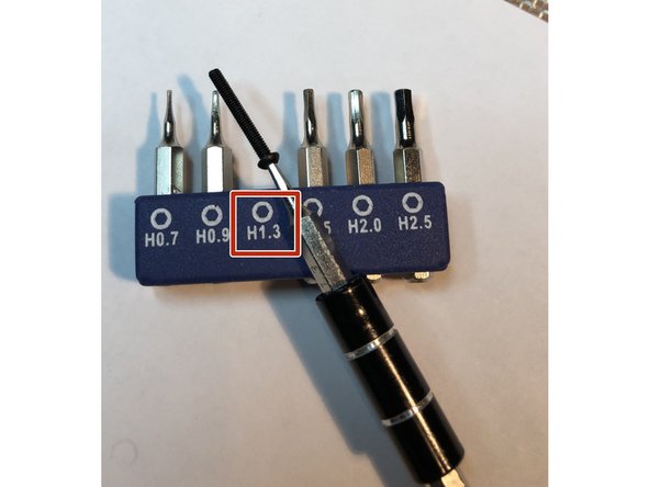
A real hex driver is essential. Attempting insertion of the M2 hex cap screw with an Allen key is guaranteed failure. Depending on your screw head, use a H1.3 or H1.5 from a micro-screwdriver kit..
-
-
-
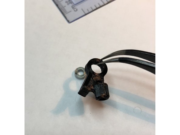
Press bearing into bottom of sensor lever.
-
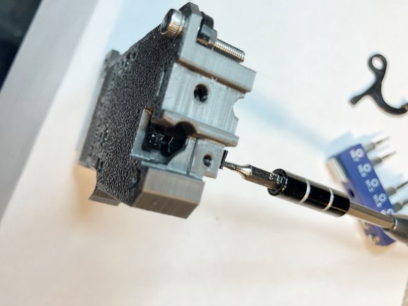
M2 black alloy screw will be used to mount optical interruptor bar on lever at 90 degrees. Pre-threading the mounting hole makes things easier later.
-
Thread M2 screw into sensor lever. Keep screw perpendicular as you thread it in. Once hole is completely threaded remove the M2 screw.
-
-
-
Slide sensor lever into extruder body.
-
M2 screw should have already been used to pre-thread and removed.
-
Temporarily secure lever with M3 screw and nut.
-
-
-
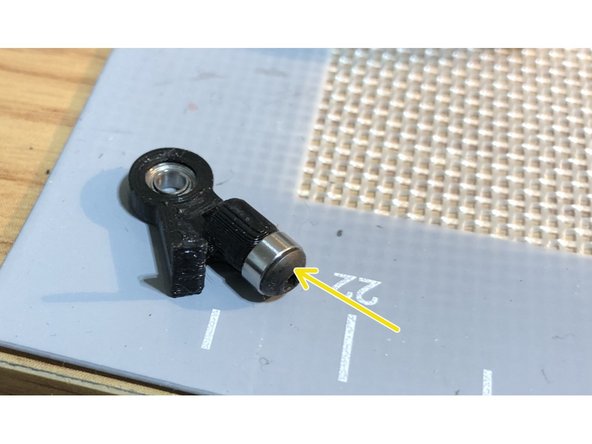
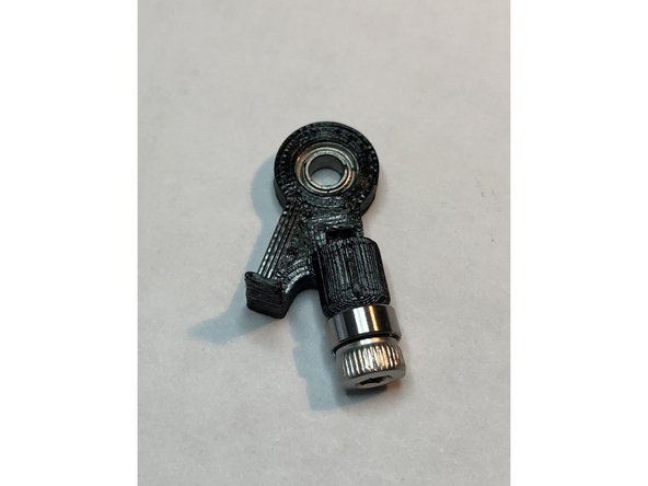
Attach optical interruptor rod to sensor lever. Its end has a shallow wedge shape to help with alignment. Rear of extruder body has opening through which a finger can support the lever
-
Fin of interruptor rod should point up. Its small leg is uppermost.
-
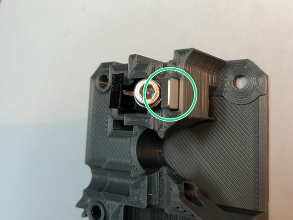
Insert 2 x 5 x 10 magnet into magnet pocket below optical interruptor bar. If you previously had magnet positioned for armature, move the magnet to this pocket.
-
Magnet pulls M2 screw downward and makes optical fin block IR sensor. When Bowden drives no longer have filament between them, idler door closes further and swings lever upward. How far it lever moves is fine tuned via a screw on idler door.
-
Here is the internal filament lever sensing filament at Bondtech https://www.youtube.com/watch?v=YfuO-00C...
-
-
-
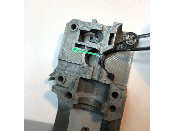
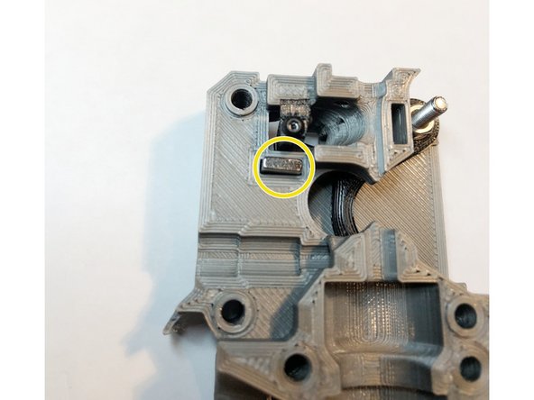
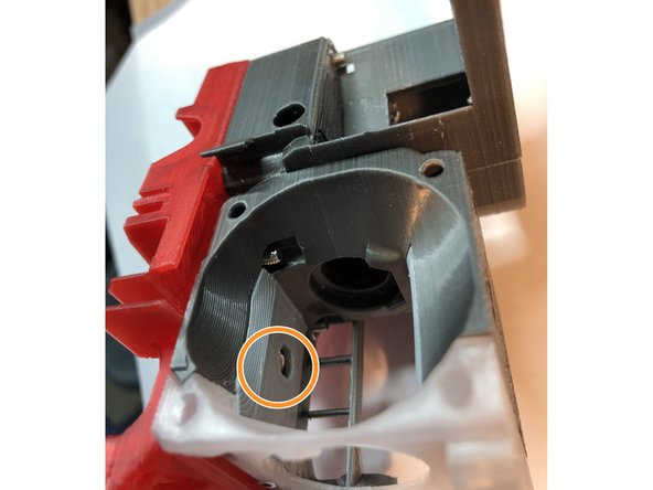
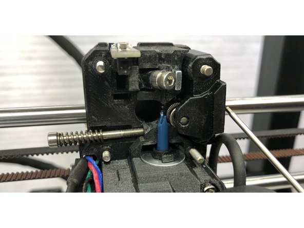
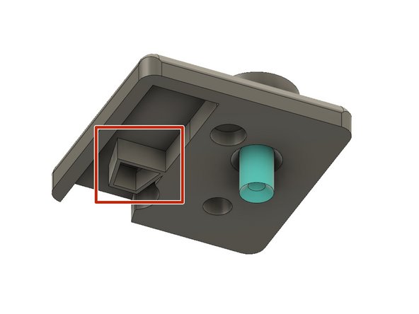
When the internal sensor lever is in use, no armature bearing prevents filament exiting the opening formerly occupied by the armature bearing. Installing a filament path insert closes that hole.
-
This part actually goes into the motor plate, but we cover it here as part of the internal lever MMU2S installation.
-
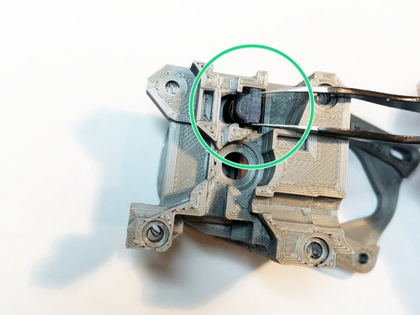
Position the filament path insert into motor plate. It is easier to handle with tweezers.
-
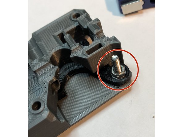
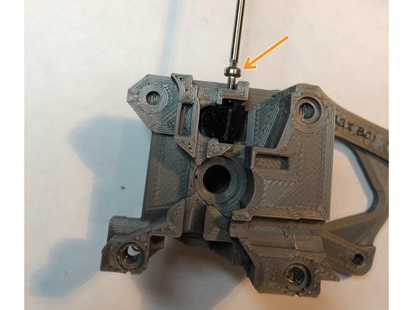
Secure filament path insert with M2 x 6 mm screw.
-
Sight down filament path and adjust insert position so filament path is enclosed but not constricted.
-
Filament path insert MUST be removed for single filament armature sensing option.
-
-
-
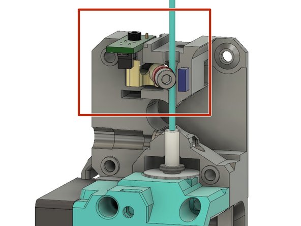
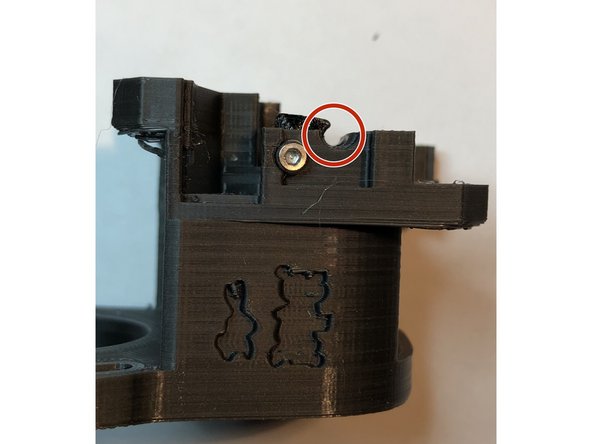
Now that the lever or armature pieces are in place, it is time to test fit the IR sensor module
-
Gently position Prusa IR Filament Sensor module and secure with M2 x 6 mm screw.
-
Do NOT use M2 screw that Prusa supplies. It is too long.
-
Verify that optical interruptor fin moves in/out of IR sensor optical path.
-
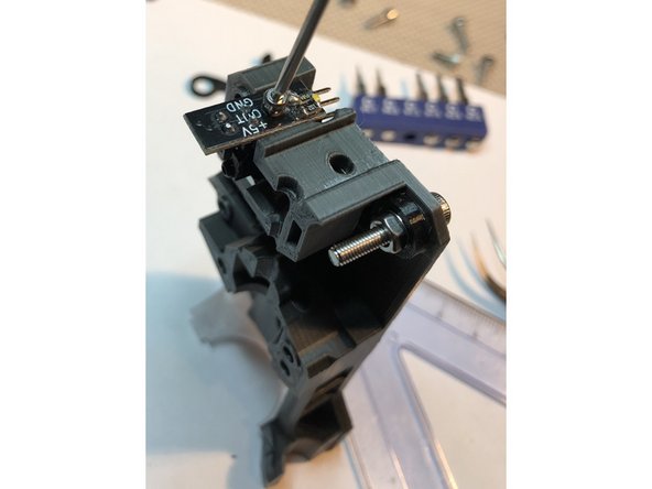
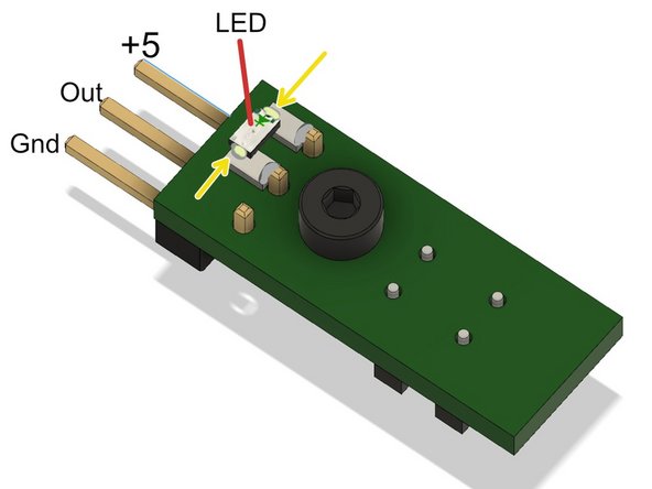
This IR sensor module has an LED indicator modification soldered onto it. Bunnies enjoy easier system testing with LED lighting up when filament is sensed. https://forum.prusaprinters.org/forum/or...
-
1K ohm total of series resistance.
-
LED in series with resistors. LED and resistor attach to V+ and Output of filament module. This requires some skill with surface mount soldering, but is a very useful modification.
-
After verifying fit, it is a good idea to remove the IR sensor module and set safely aside extruder assembly is complete. It is possible to leave it installed through the process, but it is safer to temporarily remove it.
-
-
-
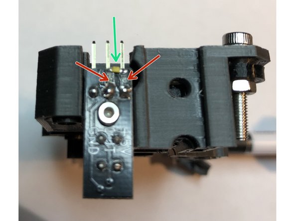
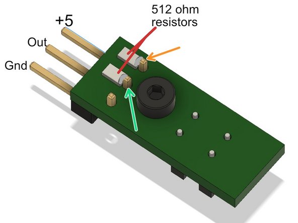
Addition of LED indicator to IR filament sensor board simplifies calibration and troubleshoot. Adds LED with 1K ohm series resistance between +5 to Out.
-
512 ohm resistor. One end soldered to +5
-
512 ohm resistor. One end soldered to Out
-
Solder LED across far ends of resistors. This completes electrical connection and physically holds LED in place.
-
If LED polarity backwards, will not light up. Anode to +5. Cathode to Out.
-
Bench test by connecting +5 and Gnd to power regulated 5 volt DC supply. Have power supply POLARITY CORRECT or you will destroy sensor. Interrupting optical path will light up LED.
-
Chanzon (5 Colors x 20 pcs = 100 pcs) 1206 SMD LED Diode Lights Assorted Kit https://www.amazon.com/gp/product/B01CUG...
-
McIgIcM 1206 SMD Resistor Kit,1206 SMD chip Fixed Resistor Kit https://www.amazon.com/McIgIcM-Resistor-...
I had a lot of trouble successfully bridging the two resistors with the LED so I went with the alternate method of using one 1K resistor on the +5V lead and the LED on the Out lead, and bridged those two with a tiny jumper wire. This gives me a slightly more compact mod, and centers the LED on the board.
-
-
-
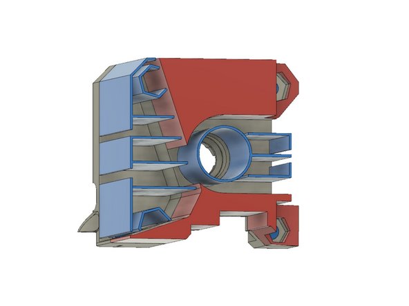
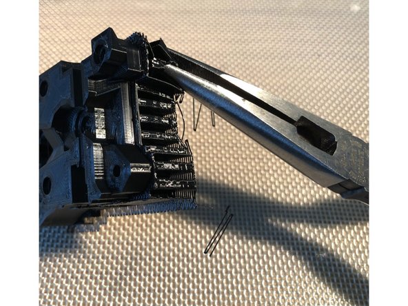
Intrinsic supports in gearbox preserve printed geometry of critical overhang areas. Formerly, slicer generated supports were used, but the new intrinsic supports yield cleaner results.
-
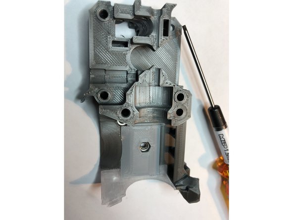
Motor plate has four M3 bolt holes that are printed with a thin, sacrificial membrane to improve print geometry. Clear out the holes with 3 mm drill.
-
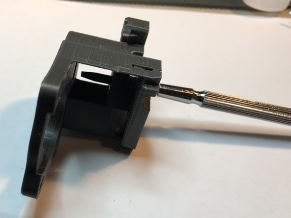
Support material inside and around bearing holes must be fully cleaned out. If necessary, pass a small, flat screwdriver in from opposite bearing hole to scrape things out.
-
-
-
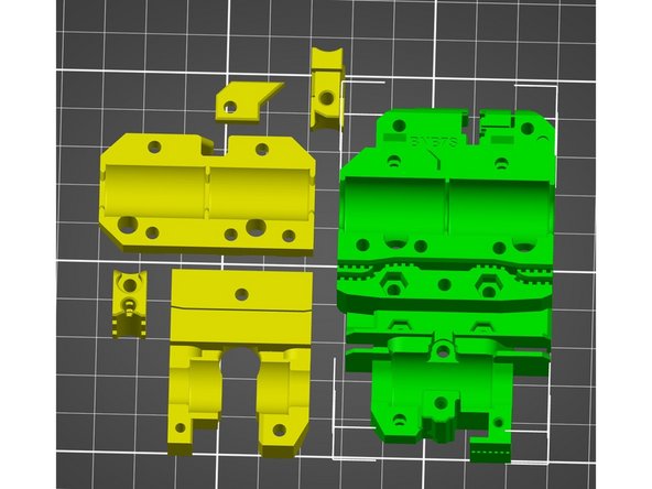
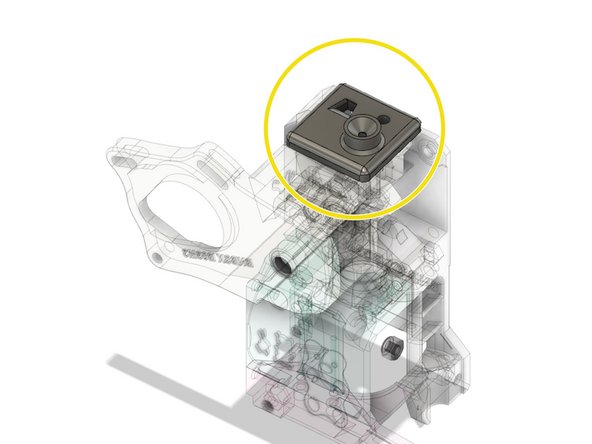
Hot End Cover
-
E3D Plenum Plate
-
M3S square nut for fan mount
-
Hot End Hot Fin
-
M3 nut for fan mount
-
Nylock M3 nut for fan shroud mount instead of regular M3 nut. Nylock helps prevent gradual fan tilt as screw loosens.
-
Two M2 x 12 mm screws
-
-
-
Hot fin holds E3D plenum plate via tabs and grooves. Do not over-tighten M2 screws. They are threading into only plastic.
-
Updated hot fins have pocket here to accept "Evan" hook of fan shroud. Hook supports right side of shroud even if screw loosens.
-
-
-
Insert M3S into slot.
-
Advance M3S to upper hole for regular fan position.
-
Push further into pocket to lower bolt hole for Volcano.
-
-
-
M3 Nylock for fan shroud
-
M3 nut for cooling fan.
-
You may now test fit complete hot end cover against extruder
-
When attaching motor plate and using filament detection armature, ALWAYS have a piece filament inserted to move armature out of way. Otherwise motor plate could crush the armature.
-
-
-
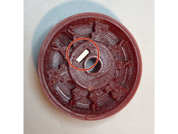
Embed M3S square nut and M3 x 4 mm set screw into pulley. Leave set screw out far enough to permit easy gear shaft passage.
-
This is a piece you must be very cautious using hot air to remove strands. Thin pulley edges are quite susceptible to deformation with a hot air gun.
-
Multiple shaft hole diameters are supplied. Best fit is one that just slips on shaft without loose wobble nor excessive tightness. Usually about 5.20 mm will work. Note hole on flat side will likely print smaller due to elephant footing. Check fitment from top and carefully ream bottom to enable best fit without creating eccentricity
-
Formerly 56 tooth pulley was supplied, but changed to 54 teeth to avoid interference with print fan mounting tab.
-
-
-
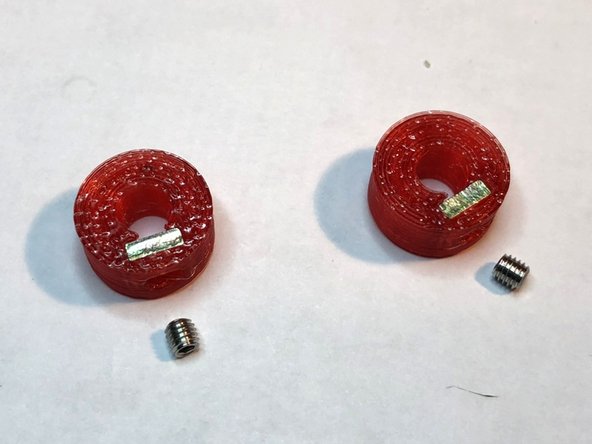
Embed M3 square nut and M3 x 3 mm set screw into each of two compact shaft locks
-
If you use longer, 4 mm long set screws, verify that they clear surround plastics during shaft rotation.
-
-
-
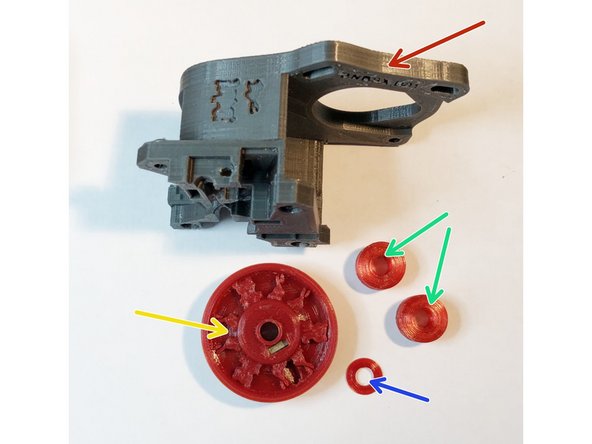
We assemble motor plate gearbox from parts previously prepared.
-
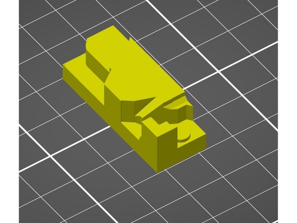
BNBSX Motor Plate Gearbox with bearings and hardware already installed
-
Bunny Science 56 tooth 2GT pulley
-
Bunny Science Spacer
-
BS compact shaft lock x 2
-
-
-
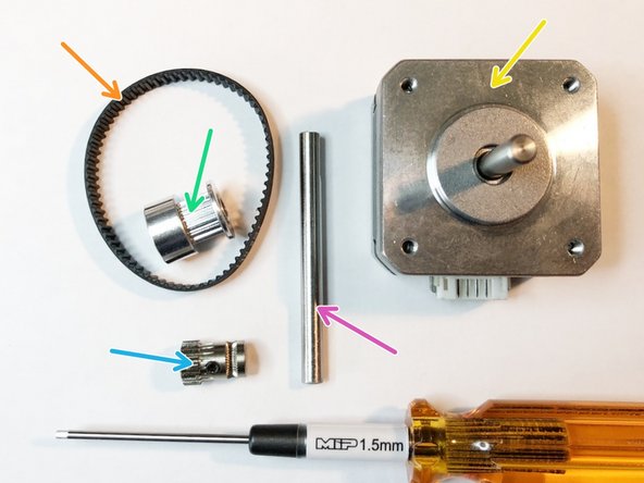
GT2 140-2GT-6 continuous loop timing belt
-
16 tooth GT2 drive pulley
-
Bondtech drive gear (with set screw)
-
STEPPERONLINE Nema 17 Bipolar Stepper Motor 0.7A 13Ncm (18.4oz.in) 17HS10-0704S
-
55 mm gear shaft with flats ground
-
If you don't already have a set of MIP drivers in your toolbox, bunnies highly recommend them. They engage hex sockets tighter and more securely than anything else they have used. Great for reducing head stripping risk.
-
-
-
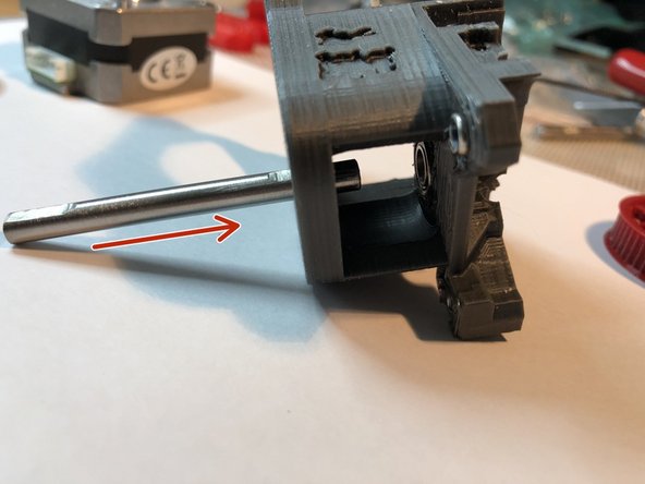
Verify that shaft lock set screws are backed out so shaft freely passes through them.
-
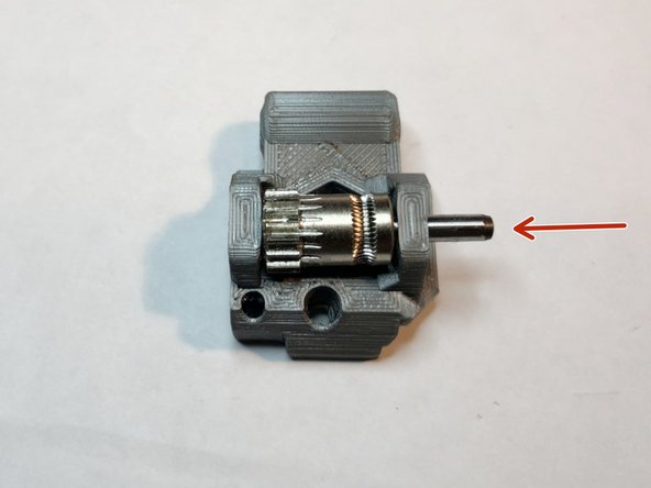
Pass Bondtech end of shaft through front bearing.
-
Put two compact shaft locks on shaft. Tapered ends of locks should be directed towards bearing, Leave set screws LOOSE.
-
Pass shaft through 2nd bearing and another 2 cm further.
Thank you for the advice, but I have already messed up and broke the thing… Now, I have to get my self new bearing, new shaft and print the part again. I will have to reassemble the original extruder and I don’t want to think about it… I should have waited for your response, my bad. This is the most difficult part of the assembly. Should have more [detailed instructions, especially on how to fit the bearings and the shaft and all. I had enjoyed the build so much up to this point…
The 3d printed parts I have received in the kit from aliexpress are from a newer revision I guess… We need to install the bearings here? My problem is the shaft won’t pass through the bearing. I don’t know if I’m doing something wrong or the shaft is too thick ? I’m stuck right here… :(
-
-
-
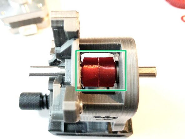
Put Bondtech drive on shaft. Align its set screw with flat and position so shaft extends about 0.25 mm beyond Bondtech.
-
Tighten Bondtech set screw
-
Slide shaft in/out to align Bondtech filament teeth groove centered with plane of filament path.
-
Secure shaft in this position with shaft locks. Each lock lightly touches its respective bearing and secures shaft in place.
-
-
-
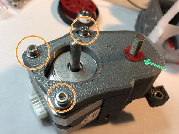
Insert motor into motor plate gearbox. Motor plate is notched and recessed for easy motor insertion. Do not secure the motor yet.
-
Mind the direction of motor connector. It must be pointed leftward or up (viewed from front)
-
Loosely secure motor with three M3 x10 mm screws and washers. Leave the screws LOOSE. You may need more than one washer if motor has shallow threading.
-
Add spacer to shaft. Flat side of spacer should be oriented up (away from gearbox).
-
-
-
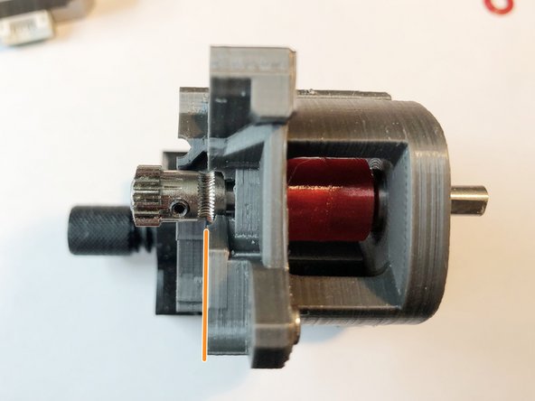
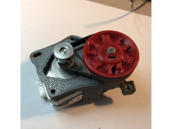
Check that pulley and drive gear set screws are loose.
-
Hold pulley, belt and drive gear together and slide all three into position simultaneously.
-
-
-
Slide large pulley down shaft until it almost contacts spacer.
-
Align drive shaft with pulley set screw. You can do so by turning the shaft.
-
Tighten large pulley set screw. With motor and belt LOOSE, you can reach in above or below belt.
-
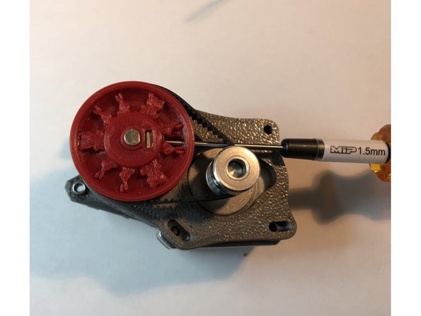
Align drive gear with belt and secure its set screws on motor shaft. Take care to engage motor shaft flat first.
-
-
-
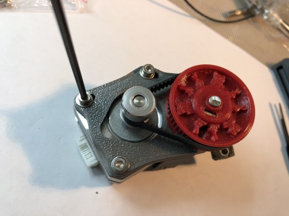
Rotate motor on its pivot bolt to take up belt slack. You don't need to make belt super taught like the X and Y belts. It simply needs slack removed.
-
Secure motor in position with its bolts
-
Motor Plate Gearbox assembly is now complete.
-
-
-
Bondtech drive door has pocket for M3S square nut. Clear out the overhangs completely.
-
Bondtech shaft must be inserted in direction illustrated. It will not fit from other side. Fully seat the shaft.
-
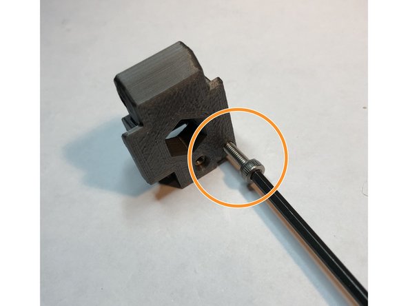
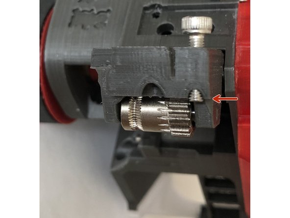
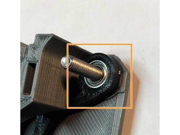
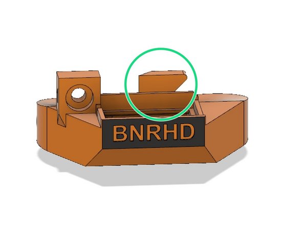
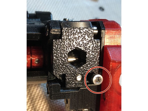
M3 x 12 mm filament sensor adjust screw directly threads into plastic of idler door. This is used to adjust internal filament sensor system. For now, advance its tip to just flush with inside surface of idler door.
-
Filament sensor adjust screw is only used with MMU2S, but it is reasonable to install one now in case of later change to MMU2S
-
User, AnatomicFlack suggests rounded reshaping tip of sensor adjust screw to produce more linear adjustment response.
-
-
-
When filament sensor adjust screw is correctly set, it minimally extends beyond idler door. This picture show how little it will extend after calibration. For now, leave its tip flush with idler door inside surface.
-
-
-
Some M3 screws in BNBSX Extruder are critical length. Although bunnies have adjusted design for standard metric screw lengths, these should be checked to verify their ends don't extend beyond associated nut.
-
Hot End Cover mounting screws must not protrude beyond rear of extruder body. B02M8 and newer use standard M3 x 30 mm. Older required custom 27 mm long.
-
Lower center extruder body mounting screw can protrude into plenum. This is especially problematic if wider, Mosquito hot end is installed.
-
Motor plate mounting screws protruding into motor bay impinge on motor body.
-
-
-
Hot end cover M3 x 30 mm mounting screws are critical length.
-
Custom length M3 x 27 mm (if hot end cover older than rev B02M8 )
-
Verify that ends of bolts do not extend beyond rear surface of extruder. Refine bolt lengths as necessary.
-
After verifying proper fit, remove hot end cover. We will re-attach it when installing hot end.
-
-
-
Prepare BNB Universal X-Carriage using directions at BNB Universal X-Carriage
-
-
-
If you have not already done so, add BNBSX spacer to back of Universal X-carriage. Its index pin should snap into the carriage.
-
BNBSX spacer is part of universal x-carriage version BNB7 forward. Its function is to permit use of a standard length M3 x 30 screw.
-
-
-
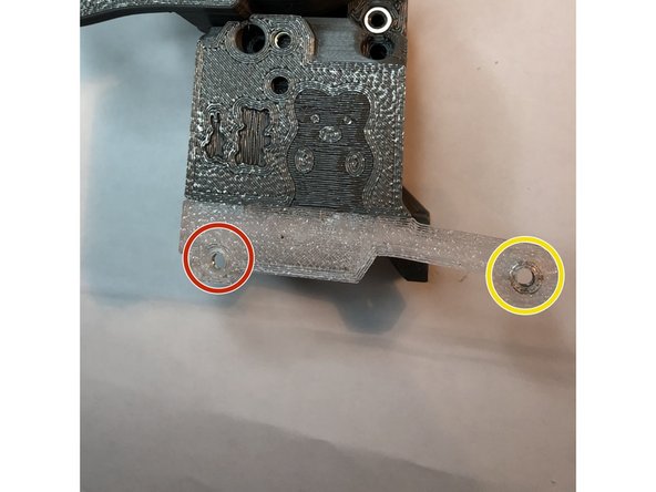
There are three critical length screws extending from back of x-carriage into extruder. Do not install them now, but remember these places to check during assembly later.
-
M3 x 30 mm (location from front, upper left motor bay)
-
M3 x 16 mm (location from front front, lower left motor bay)
-
M3 x 8 mm CAP head screw. (location from front, lower, middle plenum)
The M3x16 bolt was too short, but M3x20 seemed to work and cleared the motor
Chris Champeau - Resolved on Release Reply
-
-
-
Insert two M3 x 12 extruder body mounting screws, but leave them slightly loose.
-
Best alignment of extruder body x-carriage is achieved if final tightening of bolts is done after all bolts are inserted.
-
M3 x 30 mm motor plate mounting screw. Optionally, grind this to 27 mm for easier motor plate removal.
-
M3 x 40 mm idler door hinge screw. Just insert this one, but don't engage its Nylock yet. We are inserting now only to help with alignment.
-
Tighten screws to two finger firmness after all are inserted.
I agree M3x12 do are just too short, I am using M3x16 for now and if I need to file them down later I will
Chris Champeau - Resolved on Release Reply
It may be obvious to most, but it didn't register with me - the M3x40 idler door bolt must be the partially threaded variety for the MMU2S internal lever bearing to be properly constrained. I initially used a fully threaded bolt and couldn't get the filament sensor to work properly. As soon as I changed to the partially threaded bolt, it worked perfectly!
Jonathan Ehmer - Resolved on Release Reply
-
-
-
PTFE tubing for hot end are best sculpted for optimal filament constraint using Bunny Science PTFE Sculpting Guides for Tight Filament Constraint
-
-
Sculpting PTFE to closely match Bondtech drive gears improves flex filament handling capability.
-
-
-
Place extruder near table edge or on box to let extruder leads freely hang down. Position hot end into groove mount.
-
Align hot end rotation to make heat block square with extruder
-
Clamp hot end in place with two M3 x 30 mm screws. (If older than revision M8 parts, use custom length M3 x 27 mm)
-
Extruder is at risk of falling with extruder wires hanging off table edge.
-
-
-
Motor plate gearbox slides straight into extruder body. Registration pins create a light snap together fit.
-
NEVER remove or insert motor plate with idler door tensioned. Completely loose tensioner screw beforehand.
-
Optical armature can be crushed by motor plate. Use a filament in filament path to keep armature out of way during motor plate installation.
-
-
-
If single filament armature sensor, place 1050ZZ bearing on hinge bolt as spacer in place of internal sensor lever.
-
if MMU2S internal lever, hinge bolt goes through lever bearing then idler door
-
Secure tip of hinge bolt in Nylock, but don't tightly tension the bolt. It must not deform the plastics.
-
No white nylon washers are specified in Bunny Science design. Parts have inherent tapers to replace washers in Prusa design. However, if door has too excess play, you can add a white nylon washer.
It was previously mentioned, M3x40, however you should use a partially threaded bolt. There should be a few spare ones that come with your printer.
-
-
-
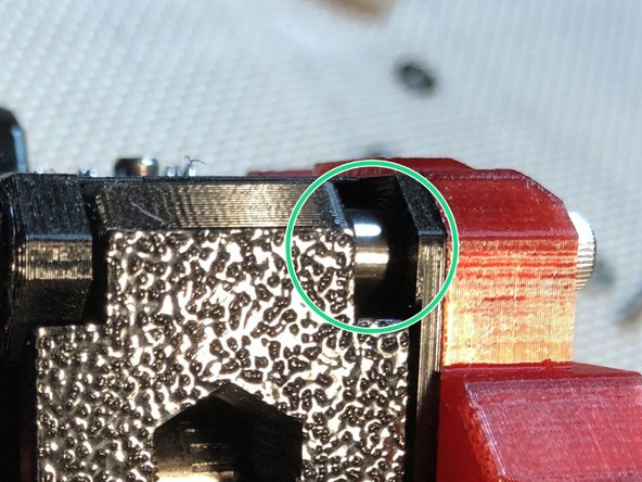
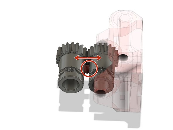
Bondtech set screw has very limited range for proper depth. If shaft flat is too shallow, the screw sticks out too far. If shaft is too deep, set screw won't secure the gear despite bottoming out.
-
Use your finger and check that drive shaft Bondtech does not wiggle on drive shaft.
-
Close idler door and hold it shut with a finger. Feel the door for motion as you rotate gear shaft through several rotations. If flat is too shallow, you will feel screw impinge idler Bondtech and slightly open door during each rotation.
-
If you find impingement by Bondtech set screw, disassemble motor plate gearbox and correct shaft flat depth now. Extruder will not work reliably unless set screw is secure at correct depth.
-
Illustration exaggerates how far set screw must stick out to impinge. Correct position is not entirely flush, but just a fraction too far out causes impingement.
-
-
-
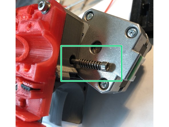
Insert idler door tension adjust screw and spring. Only one screw and spring are used in BNBSX.
-
Correct tension is typically with top of screw head completely flush with extruder body.
Probably should include that this is a 40mm bolt, or atleast it should be, I had to increase the tension a bit further than flush with the side.
Chris Champeau - Resolved on Release Reply
-
-
-
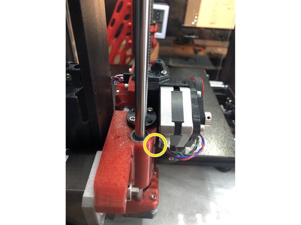
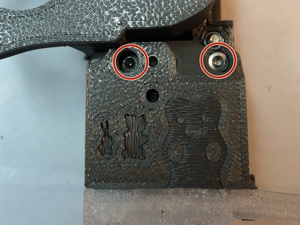
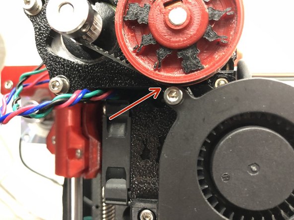
Use two M3 x 18 mm screws and LOOSELY attach parts cooling cooling fan. You can add a M3 washer to lower right screw, but not to top screw.
-
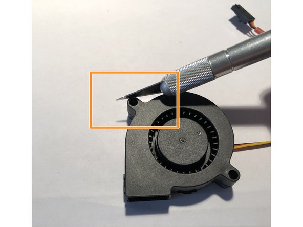
Fan's top mounting tab will impinge belt path due to unavoidable tight spacing. Bunnies could not alter this spacing without breaking important spatial relationships.
-
Shave top of fan mounting tab with Xacto knife. Reduce its top by down about 0.75 mm. Only front portion 10 mm needs modification. Fan plastic shaves readily and controllably. Remove only enough to clear belt.
-
Leave fan screws loose until after fan shroud is installed. Tightening them now makes fan shroud installation difficult.
For whatever reason I did not have this issue, the belt and gear just clear the fan and do not rub against it (I am using the misquito hot end so it is possible the fan sits just ever so slightly lower with that setup)
Chris Champeau - Resolved on Release Reply
-
-
-
Fan shroud attached to hotend cover via single M3 x 10 mm screw.
-
Current fan shroud has interlock "Evan" hook to secure right side of shroud to hot fin. hook prevents right sided downward tilt of shroud should mounting screw loosen.
-
Engage hook with hot fin while simultaneously slipping shroud over fan outlet.
-
Engage interlock hook BEFORE inserting mounting screws.
-
"Evan" hook was named after evan38109 reported right sided droop of extra wide Mosquito fan shroud when screw became loose. Although a nylock screw could solve the problem, bunnies added hook to help ensure against print crash mishaps.
-
-
-
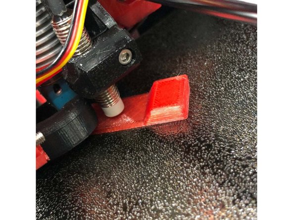
Place a piece of paper on print bed. Nozzle tip must be clean and printer powered off.
-
Manually lower x-carriage until nozzle tip just touches paper.
-
Completely loosen PINDA probe
-
Place PINDA probe squarely upon 0.8 mm thick PINDA height gauge. https://www.thingiverse.com/thing:355564.... If you lack a gauge, a zip tie is usable, but sometimes a bit too thick)
-
Clamp PINDA in position.
-
Turn printer on and raise Z to bump against top stops to level x-carriage.
-
Perform XYZ and Live-Z calibrations after completing extruder install.
-
-
-
Top covers supplied for stand alone, MMU2S, PC4-M6, PC4-M10, and Pallete 2
-
REMOVE INTRINSIC SUPPORT from around LED view port before using top covers.
-
4 mm x 10 mm long, top cover PTFE tube for standalone cover should be internally chamfered on both ends.
-
MMU2S and Palette 2 owners, pass PTFE tubing all the way through top cover and another 5 mm INTO extruder body.
-
10 mm PTFE segment is not used with covers having full pass-through. PC4-M10, MMU2S and Pallete2 covers have full PTFE pass through.
-
Frosted tape inside top cover LED observation window is an excellent diffuser.
-
-
-
Feed print fan cable into right guide slot
-
Form loop in PINDA cable and feed into right guide slot.
-
Hot end cooling fan and extruder motor cable were previously routed to left guide slot
-
PINDA, print fan, hot end fan, and extrude motor cable pass between x-rods
-
Hot end heater and thermistor cables pass below bottom x-rod
-
-
-
Orient two upper and one lower LMU8 bearings each with a bearing row up. (You cannot see row positions inside the bearings now, but we marked the row locations during x-axis assembly.)
-
Get your screws and driver ready now. You will only have one hand during next step.
-
2 of M3 x 12 mm (top row of screws)
-
3 of M3 x 18 mm (bottom row of screws)
-
Align x-carriage (with attached extruder) onto all three bearings. Hold in position while securing top x-carriage top cover.
-
Gradually and evenly tighten screws while checking that you are not causing any binding.
-
-
-
You should have already prepared the x-carriage belt paths but we will repeat instructions. There are two belt paths on x-carriage.
-
Use TOP belt path for Bear axis
-
Use Bottom belt path for Prusa axis
-
Add 4 tooth long segment of GT2 belt in unused path to reinforce thin, toothed plastic segments.
-
With tensioner bolts engaged but only screwed in 1-2 turns, insert x-belt NEARLY taught, but remaining loose. There is plenty of adjustment range. No need to stretch belt while putting into clamp.
-
-
-
In this step, we adjust the filament sensor to reliably detect presence of filament between Bondtech gears. Idler door must be tensioned during adjustments.
-
If motor does not permit manual turning of pulley for inserting/removing filament, loosen and retighten idler door tension screw to manipulate filament.
-
Insert filament into printer and advance it through Bondtech drive gears. The idler door will swing slightly outward when filament is between drive gears.
-
Display filament sensor state on LCD during this process. Better yet, watch LED indicator If you have installed LED indicator mod on IR sensor board,
-
Turn M3 sensor adjust screw on idler door CLOCKWISE (in) until sensor indicates no filament (LED goes off). Just two or three revolutions should be max.
-
Turn M3 sensor adjust screw COUNTER-clockwise (out) until sensor starts indicating filament is present. Continue another 1/2 to 1/3 counter-clockwise for reliable detection.
-
Test setting by removing and reinserting filament between Bondtech gears.
-
-
-
Geared extruder, 1.8 degree motor. Send three commands as below.
-
M350 E16
-
M92 E473
-
M500
-
Geared extruder, 0.9 degree motor . Send three commands s below.
-
M350 E8
-
M92 E473
-
M500
There were changes in how micro-stepping and e-steps are being handled. The original recommendation of E945 was when extruder motor microstepping was 32. That turned out to be difficult for EINSY to keep up with during fast MMU2S filament moves. Since that time, microstepping has been changed to 16 (for 1.8 degree motors)
Instructions in the intro have been changed to match the recommendations here.
Your slight decrease from E473 to E455 is appropriate if your extrusion measurements indicated the need.
The introduction has you set your M92 E-Steps to E945 if using prusa firmware and E473 if using Your modified firmware. I am using prusa firmware 3.7.2-2363
Here it has you set them to M92 E473.
Is there a reason for the different E-Steps.
At least now we know that E472 will work with unmodified prusa firmware.
For me M92 E455 brought me to the correct extrusion.
Thank you.
Cheers!
James Masterson - Resolved on Release Reply
-


Cancel: I did not complete this guide.
6 other people completed this guide.
Attached Documents
13 Comments
I found the variety of experiences offered by tonybet.com casino interesting. From classic titles to more modern options, I always find something that catches my eye. The best part is that navigation is fast and doesn't feel cluttered. tonybet.com casino manages to combine simplicity with good content, perfect for those who value a stable and easy-to-use platform accessible from any device.
I found the variety of experiences it offers interesting. TonyBet Chile casino. From classic titles to more modern options, I always find something that catches my eye. The best part is that navigation is fast and doesn't feel cluttered. tonybet.com casino manages to combine simplicity with good content, perfect for those who value a stable and easy-to-use platform from any device.
To check the setting, unscrew the filament from the Bondtech gears and then put it back in. The following details can pique your interest if you are not a good player or if you are simply want to try a different game. There are currently several free Basketball Legends 2020 unlock codes floating around online.
Colin Dotson - Open Reply
This is doable if you constructed your Mk3S from the ground up. All it takes is a little time. The stepper online motor that is suggested in this guide works well. I will need to place an order for a black oxide screw for the MMU2S filament lever because I do not currently have any on hand. combined, it achieves incredible results!
Colin Dotson - Open Reply
To ensure your BNBSX MKS3 Geared Extruder performs optimally, incorporating the Codex Executor into your setup can automate and refine the calibration process, making it easier to achieve precise extrusion rates.
Rita Olsson - Resolved on Release Reply
Your information is very helpful. Your website and geometry dash lite are the websites that I trust the most and update information regularly.
johnsonwin - Resolved on Release Reply
Just finished this 9/12/2021. I followed the official MK3S guide in reverse to take the extruder apart and then I followed this guide to build the BNBSX. This guide had me figuring a lot out on my own but once I got the extruder body assembled from this guide, it all made sense. If you built your Mk3S originally, you can do this. Just takes a bit of time. Working good with the stepper online motor recommended in this guide. I didn’t have a black oxide screw for the filament lever for the MMU2S so I’ll have to order for that. all together, it works amazing!
Jimmy speegle - Resolved on Release Reply
I went through the BOM and there was an issue with the links. A handful brought me straight to the black screw kit. So I put together an Amazon List for this with all of the parts so you can easily get what you need. Thanks to the author for the write up and all the stellar work that went into this!
Michael Smith - Resolved on Release Reply